- 您现在的位置:买卖IC网 > Sheet目录2002 > LT8500IUHH#TRPBF (Linear Technology)IC PWM GENERATOR 56-QFN
LT8500
14
8500f
operaTion
PWM CALCULATION BY DIGITAL MULTIPLICATION OF
CORRECTION REGISTER AND PWM UPDATE VALUES
The correction multiplier is used to automatically scale
the 12-bit PWM channel data before storing the PWM
update value for the respective channel. The correction
multiplier is disabled by the correction register disable bit
(CRD),whichistoggledbythecorrectiontogglecommand
(CMD=0x7X). When the correction multiplier is disabled,
the incoming data is stored unchanged:
PWMOUTn = CHANn(NOM)
The correction multiplier is enabled by default (CRD=0)
and scales incoming channel data according to:
PWMOUTn = CHANn (NOM)
2
3
CORn + 32
64
where PWMOUTn is the number of PWMCK cycles that
PWMn is high, CHANn(NOM) is the nth channel field in
the frame, and CORn is the nth programmed correction
setting (CORn = 0 to 63). See Table 1 for examples.
The 6-bit COR value sets a multiplier of 0.5X to ~1.5X
(exactly 1.484375, or ((63 + 32)/64)) with 64 values and
a midrange, signifying a multiple of 1.0, at 32 (0x20). In
order to avoid overflow in the PWM registers when the
multiplier is greater than 1.0, the nominal PWM update
value (CHANn) is first prescaled on chip by 2/3. This
means that the full-scale width for a channel with a mul-
tiplier of 1.0 (CHANn = 4095, CORn = 32) will result in a
PWMOUTn width of 4095 (2/3) 1.0 = 2730, not 4095.
So, a correction multiplier of ~1.5 (CORn = 63) yields a
corrected PWM width of 4052 = 4095 (2/3) 1.484375.
ThePWMOUTnwidthisalwaysroundedtothenearestwhole
number. Table 1 shows examples of PWM calculations for
selected register values. This means the maximum PWM
duty cycle with CRD=0 is 4052/4096, and with CRD=1 it
is 4095/4096.
COMMAND DESCRIPTIONS
The LT8500 implements eight commands, outlined in
Table 2. The commands (CMD) are encoded in the eight
LSB’sofacommandframe,andsoresideintheeightLSB’s
of the shift register when a frame has been completely
shifted in. The command field is executed by the rising
edge of LDI. Only the four MSB’s of the command field
are decoded for commands.
Synchronous Update Frame: CMD = 0x0X
A synchronous update frame updates PWM[48:1] with the
data in the frame, after processing through the Correction
Multiplier. The PWMR is updated when LDIBLANK goes
high. The PWMRSYNC register will be written from the
PWMR synchronously to the start of the PWM period (on
PWMCK 1). This command eliminates shortened PWM
“runt” pulses. The value in the PWMRSYNC registers
will update the PWM outputs on the next rising edge of
PWMCK. Examples are shown in Figure 6, cases B and E.
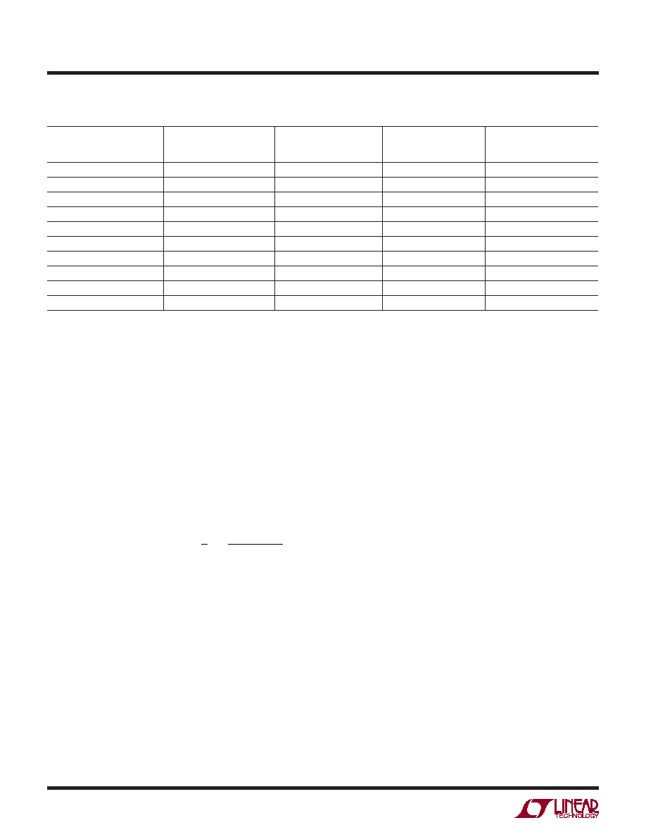
Table 1. Example PWM Width Calculations (Base 10) with Correction Enabled (CRD = 0)
A
PWM UPDATE VALUE
SENT ON SDI
B
PRESCALED PWM
(A 2/3)
C
CORRECTION REGISTER
(COR) VALUE
D
MULTIPLIER
(C + 32)/64
E
PWM WIDTH (BD)
(IN UNITS OF tPWMCK)
3
2
63
1.484375
3
120
80
63
1.484375
119
120
80
32
1.0
80
120
80
0
0.5
40
1200
800
63
1.484375
1188
1200
800
32
1.0
800
1200
800
0
0.5
400
4095
2730
63
1.484375
4052
4095
2730
32
1.0
2730
4095
2730
0
0.5
1365
发布紧急采购,3分钟左右您将得到回复。
相关PDF资料
LTC1096IN8#PBF
IC A/D CONV 8BIT SRL IN/OUT 8DIP
LTC1099ACN#PBF
IC A/D CONV 8BIT HI-SPEED 20-DIP
LTC1197IMS8#PBF
IC ADC 10BIT 500KHZ SHTDWN 8MSOP
LTC1198-1BCS8#PBF
IC ADC 8BIT 750KHZ SAMPL 8-SOIC
LTC1257IS8#TRPBF
IC D/A CONV 12BIT VOLT OUT 8SOIC
LTC1276ACN#PBF
IC A/D CONV 12BIT SAMPLING 24DIP
LTC1278-4IN#PBF
IC A/DCONV SAMPLNG W/SHTDN 24DIP
LTC1279CG#TRPBF
IC A/DCONV SAMPLNG W/SHTDN24SSOP
相关代理商/技术参数
LT-8501M
制造商:Mencom 功能描述:
LT8582EDKD#PBF
功能描述:IC REG MULTI CONFIG ADJ 3A 24DFN RoHS:是 类别:集成电路 (IC) >> PMIC - 稳压器 - DC DC 开关稳压器 系列:- 标准包装:250 系列:- 类型:降压(降压) 输出类型:固定 输出数:1 输出电压:1.2V 输入电压:2.05 V ~ 6 V PWM 型:电压模式 频率 - 开关:2MHz 电流 - 输出:500mA 同步整流器:是 工作温度:-40°C ~ 85°C 安装类型:表面贴装 封装/外壳:6-UFDFN 包装:带卷 (TR) 供应商设备封装:6-SON(1.45x1) 产品目录页面:1032 (CN2011-ZH PDF) 其它名称:296-25628-2
LT8582EDKD#PBF
制造商:Linear Technology 功能描述:DC/DC CONVRTER BOOST INVERTING SEPIC
LT8582EDKD#TRPBF
功能描述:IC REG MULTI CONFIG ADJ 3A 24DFN RoHS:是 类别:集成电路 (IC) >> PMIC - 稳压器 - DC DC 开关稳压器 系列:- 设计资源:Design Support Tool 标准包装:1 系列:- 类型:升压(升压) 输出类型:固定 输出数:1 输出电压:3V 输入电压:0.75 V ~ 2 V PWM 型:- 频率 - 开关:- 电流 - 输出:100mA 同步整流器:是 工作温度:-40°C ~ 85°C 安装类型:表面贴装 封装/外壳:SOT-23-5 细型,TSOT-23-5 包装:剪切带 (CT) 供应商设备封装:TSOT-23-5 其它名称:AS1323-BTTT-30CT
LT8582IDKD#PBF
功能描述:IC REG MULTI CONFIG ADJ 3A 24DFN RoHS:是 类别:集成电路 (IC) >> PMIC - 稳压器 - DC DC 开关稳压器 系列:- 标准包装:250 系列:- 类型:降压(降压) 输出类型:固定 输出数:1 输出电压:1.2V 输入电压:2.05 V ~ 6 V PWM 型:电压模式 频率 - 开关:2MHz 电流 - 输出:500mA 同步整流器:是 工作温度:-40°C ~ 85°C 安装类型:表面贴装 封装/外壳:6-UFDFN 包装:带卷 (TR) 供应商设备封装:6-SON(1.45x1) 产品目录页面:1032 (CN2011-ZH PDF) 其它名称:296-25628-2
LT8582IDKD#PBF
制造商:Linear Technology 功能描述:DC/DC CONVRTER BOOST INVERTING SEPIC
LT8582IDKD#TRPBF
功能描述:IC REG MULTI CONFIG ADJ 3A 24DFN RoHS:是 类别:集成电路 (IC) >> PMIC - 稳压器 - DC DC 开关稳压器 系列:- 设计资源:Design Support Tool 标准包装:1 系列:- 类型:升压(升压) 输出类型:固定 输出数:1 输出电压:3V 输入电压:0.75 V ~ 2 V PWM 型:- 频率 - 开关:- 电流 - 输出:100mA 同步整流器:是 工作温度:-40°C ~ 85°C 安装类型:表面贴装 封装/外壳:SOT-23-5 细型,TSOT-23-5 包装:剪切带 (CT) 供应商设备封装:TSOT-23-5 其它名称:AS1323-BTTT-30CT
LT8584IFE#PBF
制造商:Linear Technology 功能描述:IC BATT CELL BALANCE 16TSSOP 制造商:Linear Technology 功能描述:BATTERY BALANCER, 2.5V-5.3V, TSSOP-16, Supply Voltage Min:2.5V, Supply Voltage M